Play with 16x2 LCD Display
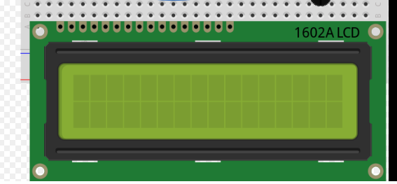
LCD display technology has been around for a long time, long before the advent of LCD TVs that have vibrant colors. In this article, we are focusing on this LCD1602 character LCD.

LCD1602 (or HD44780 as one of its key components) has two rows, each of which can display 16 characters.
Instead of calling Arduino library functions (for example, https://github.com/arduino-libraries/LiquidCrystal/blob/master/src/LiquidCrystal.cpp), we are going to dive into the timing diagrams in the original HD44780 datasheets.
It can be a lot of fun reading datasheets, and experimenting with the module. In this case, the main difficulty is to figure out two timing constraints: one is to shift the data into HD44780, the other is the time for it to execute the command/data.
HD44780 datasheet https://www.pololu.com/file/0J72/HD44780.pdf or LCD1602 module datasheet https://www.sparkfun.com/datasheets/LCD/ADM1602K-NSW-FBS-3.3v.pdf
To simplify, we only perform “write” operations, by sending either commands (when RS-line = 0) or ASCII data (when RS-line = 1), so as to display ASCII characters on the LCD display.
I am using the DE-10 LITE (with ALTERA MAX10) for experimenting. I’ve posted the essential Verilog code below, so any FPGA development board, for example ICE STICK with PMOD connector can work as well.
Since we use 4-bit mode (instead of 8-bit), there are total six output digital IO lines from FPGA to LCD1602 module: RS_LINE, E_LINE, DB[7:4]. RW_LINE is pulled to GND, since we are write-only.
1. Shift data in
E-line uses falling edge to “clock” data/command into HD44780 with clock period tcycleE (minimum) = 500ns

Since we choose 4-bit mode (to reduce IO line count: DB7 to DB4 only), it needs 2 E-line clock cycles to shift in 8-bit command or data. But it doesn’t mean the next 8-bit can follow immediately. HD44780 needs time to execute (chew on) the incoming data. In other words, we have to put delay after two E-line clock cycles.
Here is the second part of the timing constraint: execution time.
2. Internal execution time

For HD44780 to process the shifted in data/command, it needs 10 clock cycles for simple commands (in this case 37us * 270kHz = 10 cycles); or 410 cycles (1.52ms * 270kHz = 410 cycles) for “return home” command (as depicted in table 6 of the datasheet). So the subsequent command/data needs to wait at least that amount of time, till HD44780 is no longer busy.

Because we are not polling the module for the “busy” signal, we have to hardcode a delay after the command or data bits.
Ideally for a normal 8-bit command or data, using 4-bit mode, the total time = 2 x 500ns + 37us = 38us; the “return home” command takes much longer: 2 x 500ns + 1.52ms.
But after some experimenting with the Verilog code, it seems internal oscillator may not be running at 270kHz. So the 10-clock cycle can be longer than 37us. I was able to get reliable feedthrough with 50us delay after the E-line clock cycles.
Here is the Verilog code snippet of HD44780 PHY layer.
always @(posedge MAX10_CLK1_50) begin  if (count == 0)    rs_line <= rom_data[8];  if (count == 5)    e_line <= 1'b1;  if (count == 7)    DB74 <= rom_data[7:4];  // enable falling edge
  if (count == 20)   e_line <= 1'b0;  if (count == 30)   e_line <= 1'b1;  if (count == 32)   DB74 <= rom_data[3:0];  if (count == 45)   e_line <= 1'b0;end
MAX10_CLK1_50 is a 50MHz clock, with 20ns clock period. It takes about 1us to shift in 4-bit data two times. These “if count” statements follow the timing diagram of Figure 25.
localparam SHORT_DELAY = 2500;  // 50us
localparam LONG_DELAY = 110_000; //2.1msreg [16:0] count;always @(posedge MAX10_CLK1_50) begin
  if (!rst_n | start_cmd) begin
    count <= 0;
  end else begin
    if( count != (normal_delay ? SHORT_DELAY : LONG_DELAY) ) begin
      count <= count + 1;
    end
  end
end
To simplify, I use “SHORT_DELAY = 50us” for all data (RS_LINE = 1), and “LONG_DELAY = 2.1ms” for command (RS_LINE=0).
3. Debugging tips
When you first debug the PHY code, let the count loop run continuously, in order to check the E-LINE waveform on a scope.
Next use start_cmd signal to single step the command/data bytes. start_cmd can come from a button press, for example
wire start_cmd;debouncer d1 (.clk(MAX10_CLK1_50),.PB(KEY[0]),.PB_down(start_cmd));
Here is my sequence of commands/data bytes
0022          // set 4-bit mode; still in 8-bit mode
0028         // now 4-bit mode; set 2-line
0001         // clear display
000f         // display on; cursor blinking
0006         // entry mode: cursor shift right
0002         // reset display
0148         // ASCII character
...
This follows Table 12 (on page 42), which is simpler than Figure 24 (on page 46). If HD44780 power-on-reset functions properly, there is no need to do a “instruction reset” sequence.
4. Summary
This article is inspired by Mitch Davis’s YouTube video “Datasheets: 16x2 LCD By Hand (No microcontroller)”
The idea is to look into the detailed timing of HD44780. For example,
if (! (_displayfunction & LCD_8BITMODE))
{    // this is according to the Hitachi HD44780 datasheet
     // figure 24, pg 46
     // we start in 8bit mode, try to set 4 bit mode
     write4bits(0x03);
     delayMicroseconds(4500); // wait min 4.1ms
     // second try
     write4bits(0x03);
     delayMicroseconds(4500); // wait min 4.1ms
     // third go!
     write4bits(0x03);
     delayMicroseconds(150);
     // finally, set to 4-bit interface
     write4bits(0x02);
} else {
This code snippet from Arduino LiquidCrystal library uses the complicated “Figure 24” reset sequence. But if the LCD unit is powered up properly, these “internal reset” steps are not needed.
But we do need to send 0x02 twice, as explained (not very clearly) in the datasheet. Basically the default power-up setting is 8-bit mode. So the first two 4-bit E-line clock cycles may not be taken.
In addition, Arduino’s PHY puts 100us delay after E-line
void LiquidCrystal::pulseEnable(void) {
  digitalWrite(_enable_pin, LOW);
  delayMicroseconds(1);
  digitalWrite(_enable_pin, HIGH);
  delayMicroseconds(1);    // enable pulse must be >450 ns
  digitalWrite(_enable_pin, LOW);
  delayMicroseconds(100);   // commands need >37 us to settle
}
It’s certainly enough margin (larger than 37us). But from experimenting, 50us should be enough, and you now know the reason why.
