Member-only story
Calculate Load Resistor for LED Diode Circuit
There is a saying, the starting point of any software programming is to be able to print “Hello World” to a console. Similarly the simplest embedded programming task is to have MCU flash one LED using its GPIO pin.
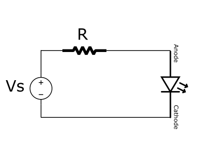
To extend that, the simplest circuit design problem is to size that resistor value R in the following LED driver circuit.

1. I-V curve
In the circuit diagram above, Vs is the voltage source which is usually pre-determined as +9V, +5V or +3.3V. LED diode is chosen from one of many colors, thus having different I-V characteristics. The design goal is to decide what R value to use, to light up the LED with a certain current draw. In other words, to have LED bright enough without burning too much power. (We simplify the design problem a little bit, PWM isn’t considered here.)
If we split the single circuit loop into two halves. Looking into the right half, we see the single component: LED diode.

LED diode I-V curve, depending on its color, can be found in a bunch of diagrams…
